VLAN 实现单网口软路由
起因是发现在原本的两个路由器间架设 wireguard 隧道,其中一个路由器 (小米 4A 千兆版) 遇到了 CPU 瓶颈,导致带宽只能达到 100-200 左右。后面研究了市面上的各种路由器的 CPU 型号,包括矿渣路由器。购买了一个 100 元的可以刷 openwrt 的竞斗云 2.0,带宽可以达到 200-300M,但仍远低于理想的千兆。目前即便是 500 元以上的高端路由器,其配置仍然只有 4 核 Cortex A53@2.0GHz 的水平。
偶然看到用旧笔记本做软路由的视频,遂萌生了折腾软路由的想法。仔细研究其方案后发现为 pppoe 拨号上网的方式,不适用于 dhcp 上网的情况。后偶然发现所购买路由器支持 vlan 功能(其实后面发现所有 openwrt 路由器都支持),于是自己独立构思了后面的架构图。并尝试成功 (11/5),最终在红米 AX6S+ 软路由的情况下,达到了 500M 的带宽,此时 AX6S 的双核 Cortex A53@1.2GHz CPU 占用率也达到了 100%。
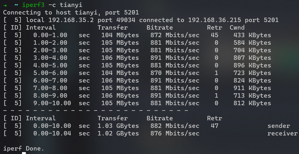
之后再接再励,将 AX6S 也配置了 vlan,并在旧笔记本实现软路由。最终带宽达到了 880Mbps,scp 文件达到 98MB/s 的速率。并且之后还成功配置了 Guest WIFI,将其和主网络隔离开来,更加保证了安全性。
通过本次项目,学会了:
- linux 下,ip, netplan 创建 bridge 和 vlan
- lxc 容器的使用
- openwrt DSA 架构配置 vlan
弄完后,在网上搜索了一下相关实现,发现提到单网口软路由,有几种情况:
- 默认是 pppoe 上网方式,该方式比较简单,不涉及 vlan 的设置,但是不适用于 dhcp 上网的情况。
- 旁路由,之前我也写过使用树莓派实现透明代理。该方式需要修改上网设备的网关为旁路设备。
- 网上争论比较多的是是否会有两次 NAT,其实不论怎样,主路由必然要起到一次 NAT。这样的话,主路由的性能至少不能太弱。当然如果家里只有 100M 的宽带,这种方式也许足够。但是如果旁路设备的性能很强的话,性能还是白白浪费了。不如这里介绍的 vlan 方式。
- 也看到了使用 vlan 实现我这种软路由的玩法,但是需要一个硬件交换机。知道使用普通 openwrt 设备就可以实现 vlan 的还是不多。
参考
- 司波图:使用笔记本 + PVE,单网口实现软路由:一个网口也能做软路由?闲置电脑再利用! - YouTube
- 不过这里的结构只适用于 pppoe 上网方式,对于 dhcp 上网方式则不适用(此结构中只有软路由一个 dhcp 服务器,不用考虑 dhcp 冲突。对于 dhcp 上网方式则需要使用 vlan 隔离 ISP 的 dhcp 和软路由的 dhcp 服务)
- 结构:
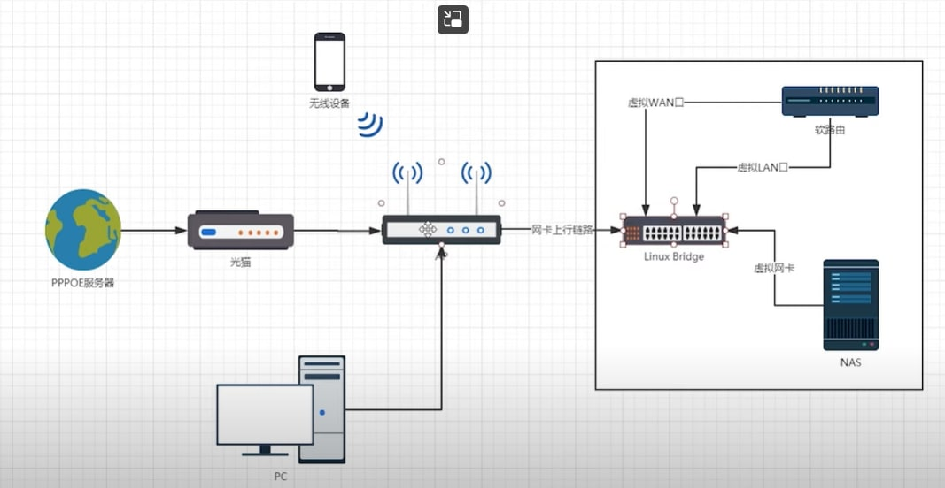
- 利用树莓派 + LXC 运行多个服务,并使用 Openwrt 作为防火墙管理:www.makikiweb.com/Pi/lxc_openwrt.html
单网口实现软路由
架构图
switch:
- 绿:端口
- 橙:设备
- 虚线:虚拟设备
- 蓝:网桥
- 灰:网络接口
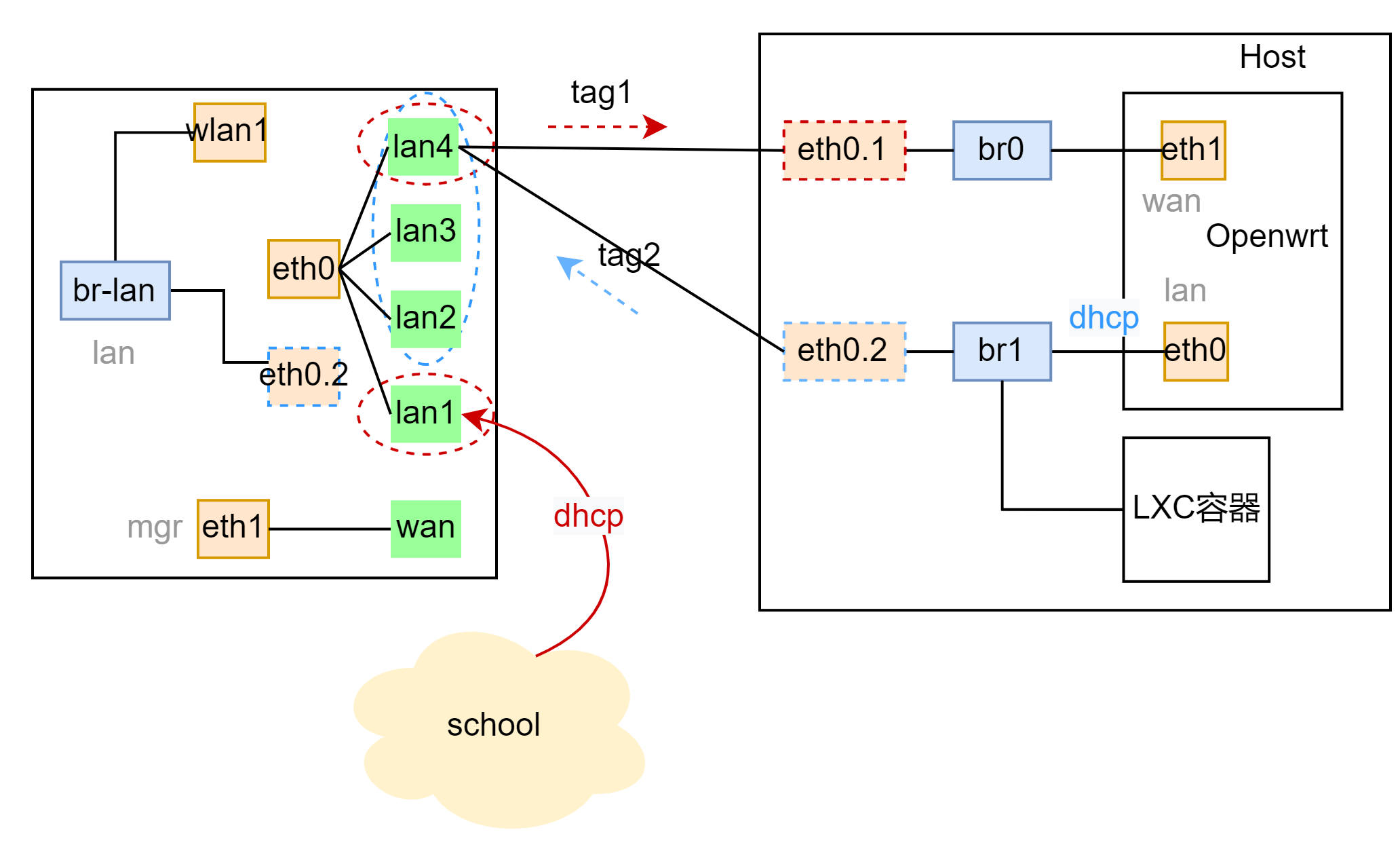
DSA
- 橙:设备
- 虚线:虚拟设备
- 蓝:网桥
- 绿:网络接口
1. 设置 host
lxc
安装 lxd
创建一个包含两个网络接口的 profile,用于 openwrt。(还可以创建一个只包含 br1 的 profile,用于其余 lxc 容器)
内容
config: {}
description: 2 interfaces
devices:
  eth0:
    name: eth0
    nictype: bridged
    parent: br1
    type: nic
  eth1:
    name: eth1
    nictype: bridged
    parent: br0
    type: nic
  root:
    path: /
    pool: default
    type: disk
name: twointf
拉取 openwrt 镜像
bridge, vlan
设置 netplan,按照 bridge, vlan 节,创建两个 vlan 和 br0, br1。
2. 路由器 vlan 设置
见后面 DSA 设置节
性能测试
从实验室到寝室的 wireguard 隧道可以达到 500Mbs 的速率,将两核 Cortex A53@1.2GHz 几乎跑满。而原本通过路由器 (4 核 MIPS 1004kc@880MHz) 则仅能跑到 200Mbs。
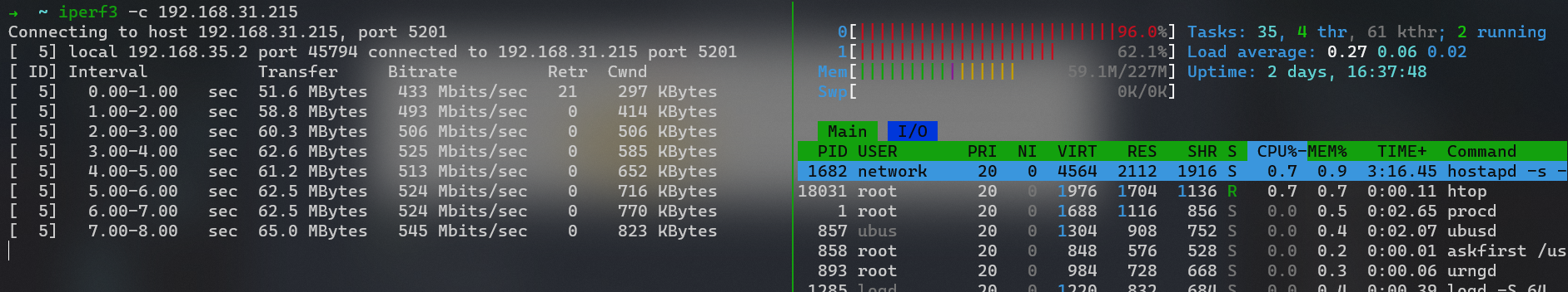
两边均使用软路由后达到千兆水平,scp 可以达到 98MB/s 的速率。
创建 bridge, vlan
iproute2(临时设置)
lsmod |grep 802

#添加vlan和bridge
sudo ip link add link enp7s0 eth0.1 type vlan id 1
sudo ip link add link enp7s0 eth0.2 type vlan id 2
sudo ip link add name br0 type bridge
sudo ip link add name br1 type bridge

#set up
sudo ip link set dev br0 up
sudo ip link set dev br1 up
sudo ip link set dev eth0.1 up
sudo ip link set dev eth0.2 up

#设置bridge master
sudo ip link set eth0.2 master br1
sudo ip link set eth0.1 master br0
netplan/networkmanager
nmcli 命令还行,不过配置复杂网络时还是使用 netplan 配置文件的方式更加适合
nmcli con add ifname br0 type bridge con-name br0
nmcli con add type bridge-slave ifname enp7s0 master br0
nmcli con up br0

nmcli con add type vlan con-name vlan1 dev enp7s0 id 1
netplan/networkd(推荐)
ubuntu 桌面版,netplan 底层使用的默认时 NetworkManger。服务器版则是 networkd,networkd 的配置文件使用起来更简单些。
配置文档:Canonical Netplan
配置:
network:
  version: 2
  renderer: networkd
  ethernets:
    eth0:
      dhcp4: false
      dhcp6: false
  vlans:
    eth0.1:
      link: eth0
      id: 1
    eth0.2:
      link: eth0
      id: 2
  bridges:
    br0:
      interfaces:
        - eth0.1
    br1:
      dhcp4: true
      interfaces:
        - eth0.2
配置完成后,需要应用修改
设置网卡固定名称
默认情况下,当机器 PCIE 设备变化时,网络接口名字可能会发生变化(比如拔插显卡)。解决办法
vim /etc/udev/rules.d/80-net.rules

# 80-net.rules
SUBSYSTEM=="net", ACTION=="add", DRIVERS=="?*", ATTR{address}=="7c:10:c9:a2:53:d8", NAME="eth0"
SUBSYSTEM=="net", ACTION=="add", DRIVERS=="?*", ATTR{address}=="38:fc:98:8d:f8:7e", NAME="wlan0"

update-initramfs -u -k all    # -u (updates initramfs), -k all(specific all kernel version)
Openwrt VLAN 设置
- 官方文档:[OpenWrt Wiki] VLAN
vlan Q & A
- vlan 作用是什么?:分离不同设备(位于同一个 LAN)。优点:不用设置子网段和路由。
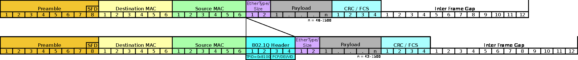
- vlan 标准:IEEE 802.1Q。vlan 会在以太网帧中添加 4 字节,因此通信双方必须要都能识别 vlan
- 哪些设备支持 vlan?:基本上所有设备都支持 vlan(软件的或者硬件交换机)。
- 对于有多个端口的嵌入式设备,内部通常会包含一个VLAN-capable switch,或者称 managed switch。管理交换机和设备内部的一个 ethernet 接口连接在一起。管理交换机可以为每个端口设置 vlan id,并且可以独立于 CPU 工作。
- 对于 PC 或则单板计算机,每个端口都有一个独立的以太网控制器 (nic),vlan 通过操作系统驱动实现。
- 如何查看自己设备是否有硬件 switch?
- 通过
ls -l /sys/class/net可以查看物理的网络接口 - 用过的小米路由器均没有专门的 switch 页面,后面才知道是采用了 DSA 架构,每个端口都显式为一个设备,如 lan1, lan2, wan。实际上均是位于 eth0 下。
- 通过
tag, untag
可以创建一个或多个 vlan id,不同 vlan 对应一个广播域
port membership:每个端口可以属于一个或多个 vlan
- tag: 该端口的包都带有 vlan id。端口连接的对面必须是 vlan awareness 的
- untag: 从该端口出去的包被删除掉 vlan id。用于和非 vlan 系统交互 port PVID 从该端口进入的 untagged 的包,被划分为哪个 vlan。(如果该端口有 untag 的 VLAN id,则必然就是等于该 vlan id。如果该端口全部都是 tag 的,则需要额外指定)
在 Cisco 术语中,untag 端口叫做 vlan port,tag 叫做 trunk port。
- PVID 即 untagged VLAN,每个端口只能指定一个 PVID。这样当该端口收到untagged 包时,便将其归为某个 VLAN 域。
- untag 接口:用于连接非 vlan 网络
- trunk 接口:感觉指的是该端口上全是 tagged,用于一根线传输多个子网。
- tag 和 untag 混合:目前不知道有什么作用
- eth0,eth1 含义:switch 自身有若干端口(路由器外侧的端口),内部到 cpu 有两个端口
- 中间解释了 VLAN 的工作过程,其中 PVID 用于处理 untagged 情况
- 接着解释了 cpu 端 接口 tag 的作用,通过指定 tag,会创建“子接口”(如 eth0.1),这样每个子接口都可以有独立的地址。
There are two places that tagging is important, leaving out "one-armed" configurations; in the switch and on the interface itself. The switch works by "wiring" all ports that have the same VLAN together. When a packet arrives at a port, if it is untagged, it is given the PVID as a tag. If it is already tagged and it is a "permitted" VLAN tag, it retains the tag. Depending on the specifics of the switch and its driver, if it is not a permitted tag, the packet may be dropped (I haven't seen config parameters for this behavior nor looked for it in detail). Inside the switch, if the destination MAC address is on a port that permits the VLAN, then it is sent out that port. For broadcast packets, it is sent out all ports that permit that VLAN. If the port is tagged for that VLAN, the tag is retained. If the port is untagged for that VLAN, the tag is dropped. The interface can also have tags, each of which creates a "sub-interface" that can be accessed by the kernel, and through the kernel user-space applications. Each sub-interface "filters" to that specific VLAN, and tags outgoing packets with the VLAN. Each sub-interface (or bridge over that sub-interface) typically has its own IPv4 address, and its own set of IPv6 addresses. This allows "trunking" where one physical wire (which may be inside of the SoC or on the PCB) handles multiple subnets or streams of data. If you're only carrying one stream of data to/from a physical interface, you don't really need to use tagging as the switch's use of PVID is sufficient. Personally, when I can, I always use VLAN tags for clarity and future extensibility. That said, my network infrastructure uses many VLANs for segregation of traffic, monitoring, and firewalling. If you tag both eth0 and eth1 to the same VLAN, that should be OK, as long as they don't have the same IP address. It's like plugging them both into the same Ethernet cable. Most of what you describe will "work" if both the interfaces and the switch are configured properly, if you only have one stream of data to/from each of the physical interfaces.
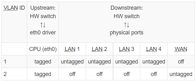
硬件 switch vlan
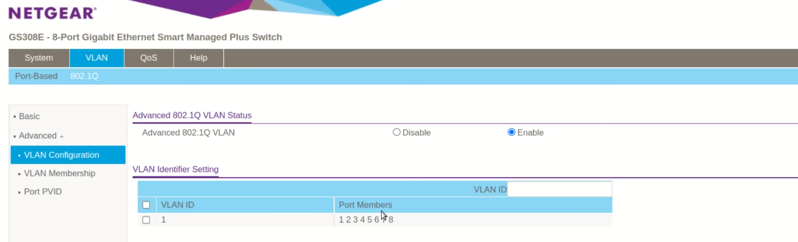
下图为一个常见的 5 端口路由器的 vlan 设置,该路由器只有一个网络接口 (eth0),包含一个内置的交换机,通过 vlan 将 WAN 和 LAN 隔离。
对于 swtich 实现的 vlan,openwrt 有一个页面用于图形化地设置 vlan。(使用 DSA 架构后就没了,见后 DSA 节)
- tagged: The tagged port (
tis appended to the port number) is the one that forces usage of VLAN tags, i.e. when the packet is outgoing, the VLAN ID tag withvlanvalue is added to the packet, and when the packet is incoming, the VLAN ID tag has to be present and match the configuredvlanvalue(s). - untagged: The untagged port is removing the VLAN ID tag when leaving the port – this is used for communication with ordinary devices that does not have any clue about VLANs. When the untagged packet arrives to the port, the default port VLAN ID (called
pvid) is assigned to the packet automatically. Thepvidvalue can be selected by theswitch_portsection.
软件 vlan
每个物理接口 (nic) 可以通过 vlan id 虚拟出多个虚拟接口(如 eth0.1, eth0.2)。当包路由到对应虚拟接口时,包离开物理接口时会打上对应 tag。当物理接口接收到对应 tag 的包时,则会路由到对应虚拟接口(不存在则会 drop)。
A driver-level VLAN could be created in the
interfacesection by adding a dot (.) and the respective VLAN ID after the interface name (in theifnameoption), likeeth1.2for VLAN ID 2 oneth1. When any internal software routing decision sends the packet to the software VLAN, it leaves the respective interface (eth1in our example) with the VLAN tag present and VLAN ID set to the number corresponding to the interface name (2in our example oneth1.2). if the incoming packet arrives to the interface with software VLANs (incoming packet toeth1) and has a VLAN ID tag set, it appears on the respective software-VLAN-interface instead (VLAN ID 2 tag arrives oneth1.2) – if it exists in the configuration! Otherwise the packet is dropped. Non-tagged packets are delivered to non-VLAN interface (eth1) as usual.
当把 non-VLAN 接口和 VLAN 接口桥接时,操作系统负责增加和删除 tag
When you bridge non-VLAN and VLAN interfaces together, the system takes care about adding VLAN ID when sending packet from non-VLAN to VLAN interface, and it automatically removes the VLAN ID when sending packet from VLAN interface to non-VLAN one.
DSA 设置
Distributed Switch Architecture(DSA) 是 linux kernel 对网络架构的一个调整,openwrt 从 21 的版本开始使用该架构。 参考:
- 推荐仔细观看:VLANs in OpenWrt 21 - YouTube
- 官方 wiki:[OpenWrt Wiki] DSA Mini-Tutorial
DSA vs swconfig
openwrt 19 以前版本使用 swconfig,从 21 的版本开始使用 DSA。
区别总结:
- 21 可以显式定义 vlan device(802.1q),19 则是在 interface 通过选择 device 时手动添加后缀,隐式配置。
- 指定端口标签方式
- 19 中,专门的 switch 页面,指定不同端口如何打标签
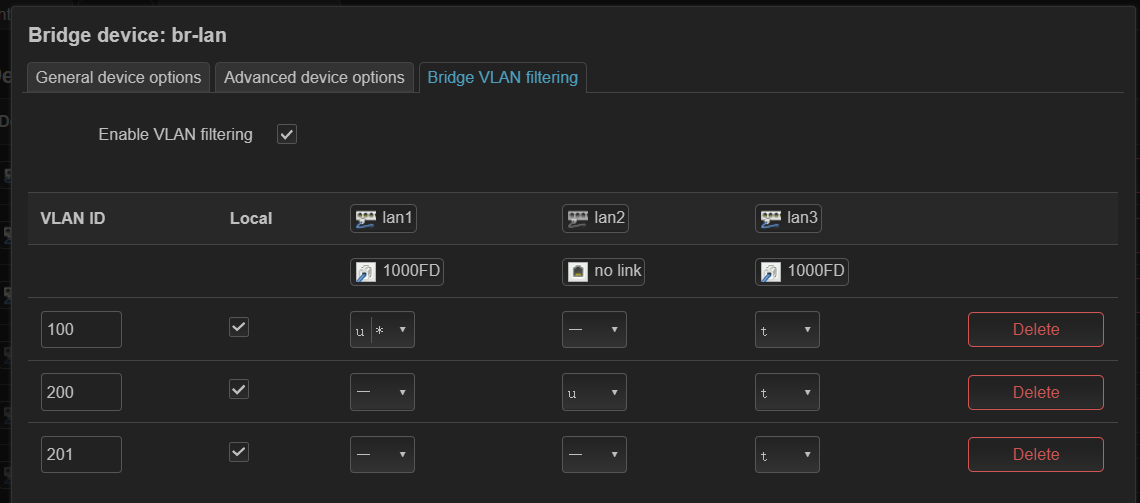
- 21 中,每个 port 变成单独一个 device(如 lan1, lan2, wan)。可以创建一个 bridge 添加 lan1, lan2, wan,然后通过 bridge vlan filtering 来指定不同端口的打标签方式。
21 总结
- define VLAN on the bridge
- tag and untag on the bridge
- attach wifi to the interface
ingress vs egress, tagged vs untagged 含义
- egress tagged:发往 VLAN 100 的包,会从指定端口发出,并且在以太网帧中插入 tag。适用于对面也是 vlan-aware 设备
- egress untagged: 发往 VLAN 100 的包,会从指定端口发出,并且在以太网帧中移除 tag。适用于连接普通设备,一个端口只能对应一个 untagged vlan。
- 对于入站的情况,如果包有 tag,则直接发往对应的 vlan。如果是 untagged 的,则添加 PVID,发往对应 vlan。
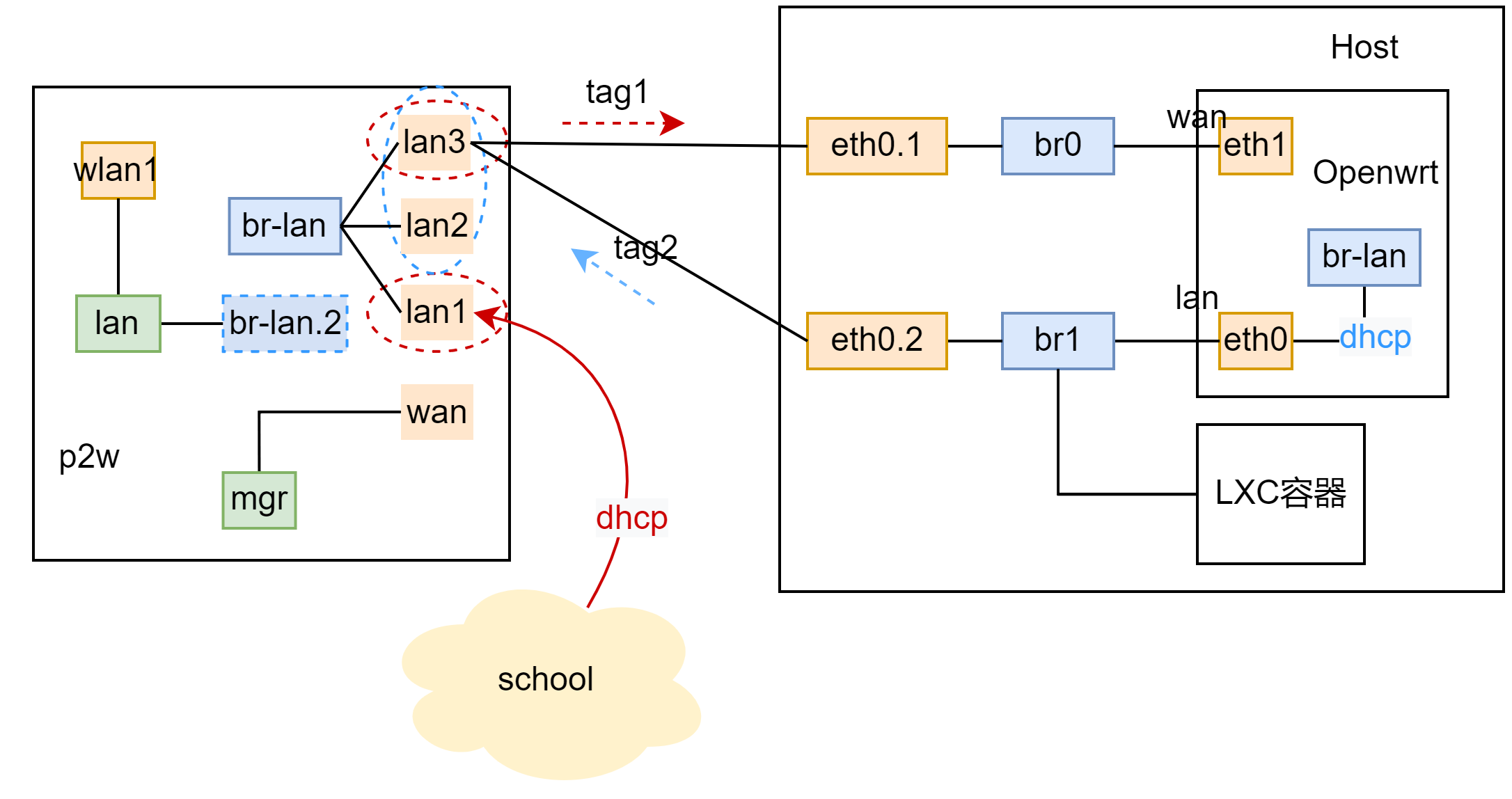
swconfig 配置实例 (p2w)
并非 21 后的版本都使用了 DSA,这里 p2w 使用的 op 版本为 22.03,仍然有 switch 页面。
设置 vlan 的过程为
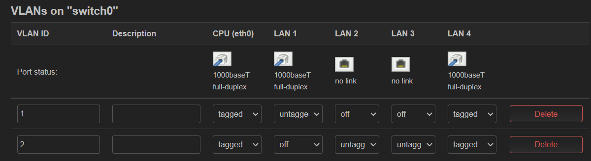
- 在 switch 中设置端口 tagged, untagged,见图 1
- 图中 vlan100 的 CPU 设置了 off,这是因为我们不需要处理该部分流量(该部分是学校到软路由虚拟链路)。这样设置不会产生 eth0.100 的设备。
- 图 2 为隐式产生的 vlan device
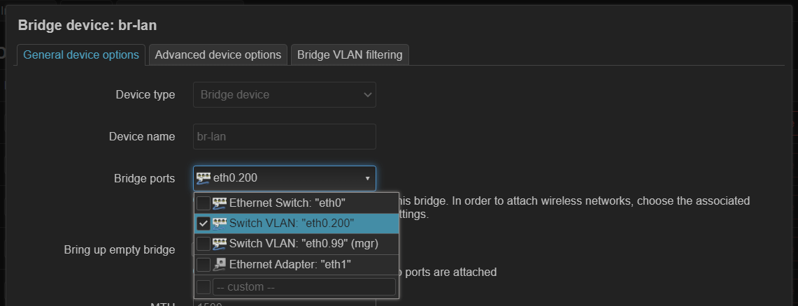
- 添加 interface,指定使用的 vlan。图 3 mgr 指定了 eth0.99,而 lan 指定的 br-lan 连接了 eth0.200
图 1
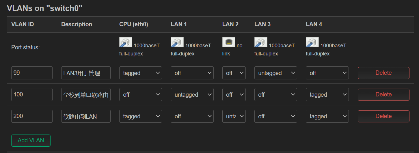 图 2
图 2
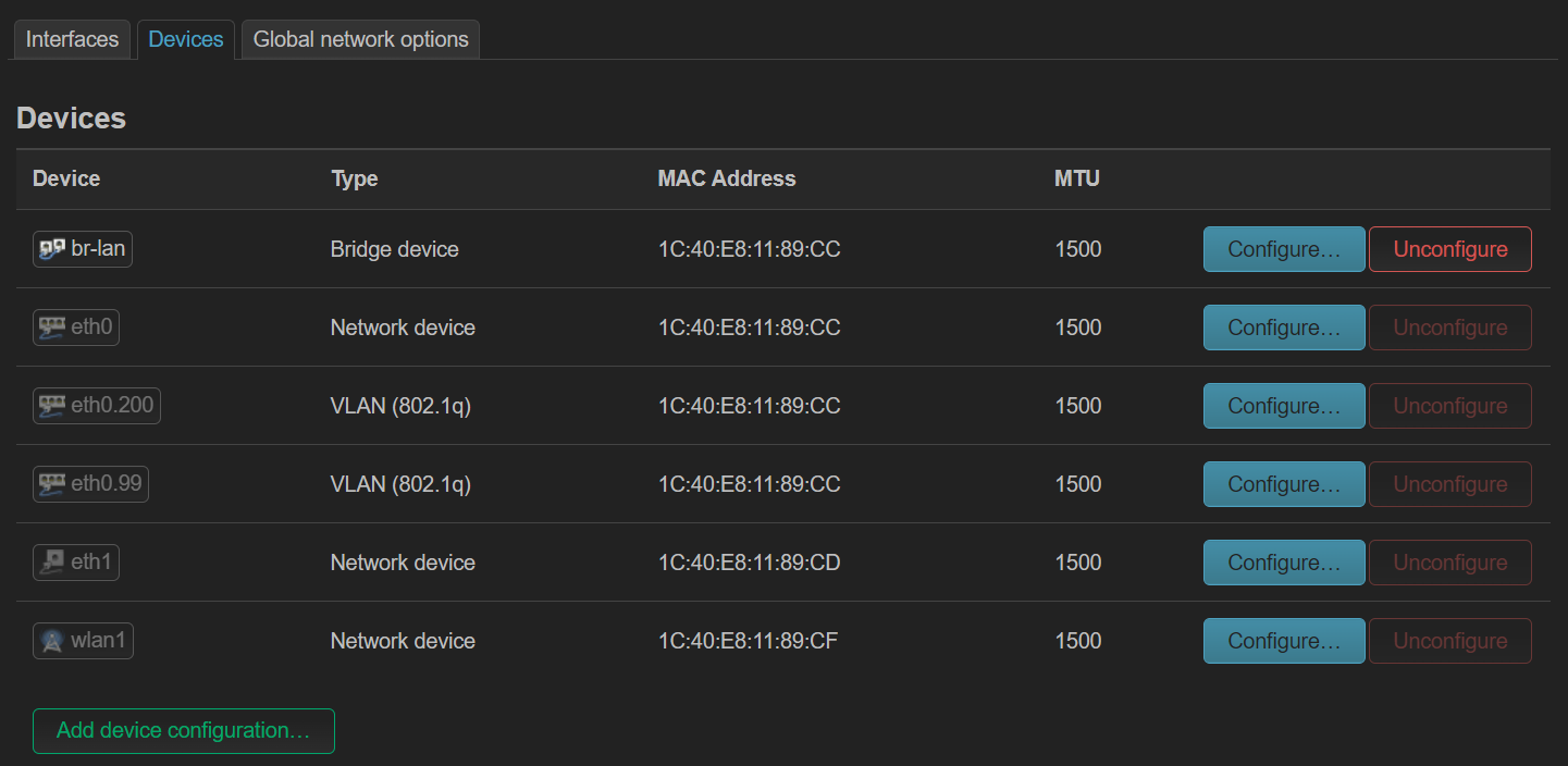 图 3
图 3
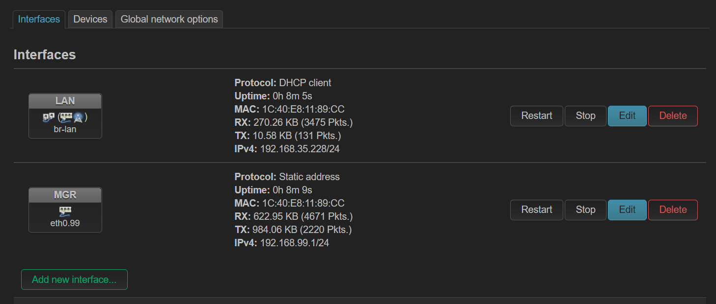 图 4
图 4
从配置文件来看,通过 switch_vlan 指定了不同端口如何打上 tag
config switch
        option name 'switch0'
        option reset '1'
        option enable_vlan '1'

config switch_vlan
        option device 'switch0'
        option vlan '1'
        option vid '100'
        option ports '4 1t'
        option description '学校到单口软路由'

config switch_vlan
        option device 'switch0'
        option vlan '2'
        option vid '200'
        option ports '0t 3 1t'
        option description '软路由到LAN'

config switch_vlan
        option device 'switch0'
        option vlan '3'
        option vid '99'
        option description 'LAN3用于管理'
        option ports '0t 2'
DSA 配置实例 (ax6s)
ax6s 有四个端口
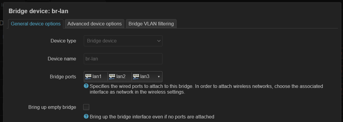
- 图 1,将所有 lan 口添加到 br-lan(这里其实 wan 也可以添加进来)
- 图 2,设置端口标签
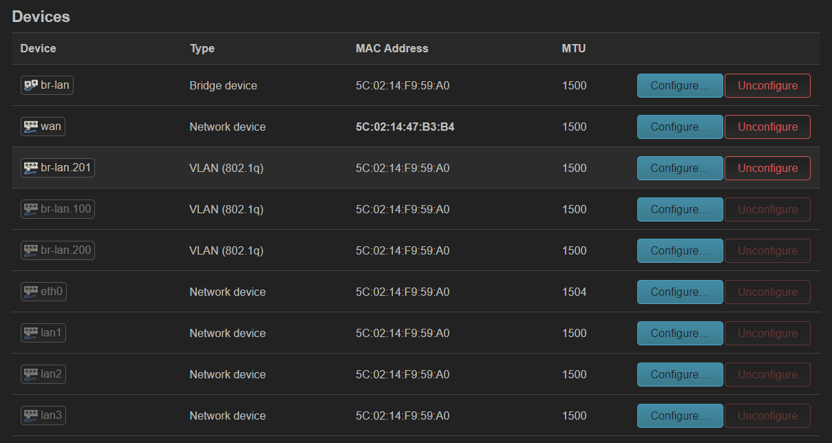
- 图 3,自动生成了 vlan 设备,但这次是在 br-lan 上生成的
- 图 4,创建接口,指定不同 vlan 设备
- 这里 wan 口专门用于管理
- 这里 wan 口专门用于管理
遇到的问题
lxc openwrt dnsmasq
- lxc 创建 openwrt 容器,刚开始为手动创建镜像。结果启动容器后发现 openwrt 内无发上网,进一步发现是 dnsmasq 没有启动导致域名解析不了。
- 按照 openwrt 论坛中的方法注释掉 dnsmasq 的启动脚本中的部分行,问题解决。Procd jail not work in lxc, dnsmasq fail to start - For Developers - OpenWrt Forum
- 现在 lxc 有 openwrt 官方镜像,没这个问题,但是其 lan interface 配置用的还是 ifname,openwrt luci 会提示更新。
log 是不是相关
[Tue Jul 25 17:55:09 2023] audit: type=1400 audit(1690278912.535:306): apparmor="DENIED" operation="mount" info="failed type match" error=-13 profile="lxd-op1_" name="/tmp/ujail-LFABnj/bin/sh" pid=920178 comm="ntpd" flags="ro, remount, bind"
p2w 的 wan 口坑
wan 口用于管理怎么都不行。一修改 swtich 菜单,马上失联。使用 lan 口管理成功
wifi 挂载到网桥上才能获得 dhcp 地址
- eth0.200 用于 lan,lan 设置 dhcp client,但是 p2w 获得到了 ip,连接 wifi 的笔记本获得不了。创建一个网桥 br-lan,然后添加 eth0.200 后成功。
guest wifi 无法上网
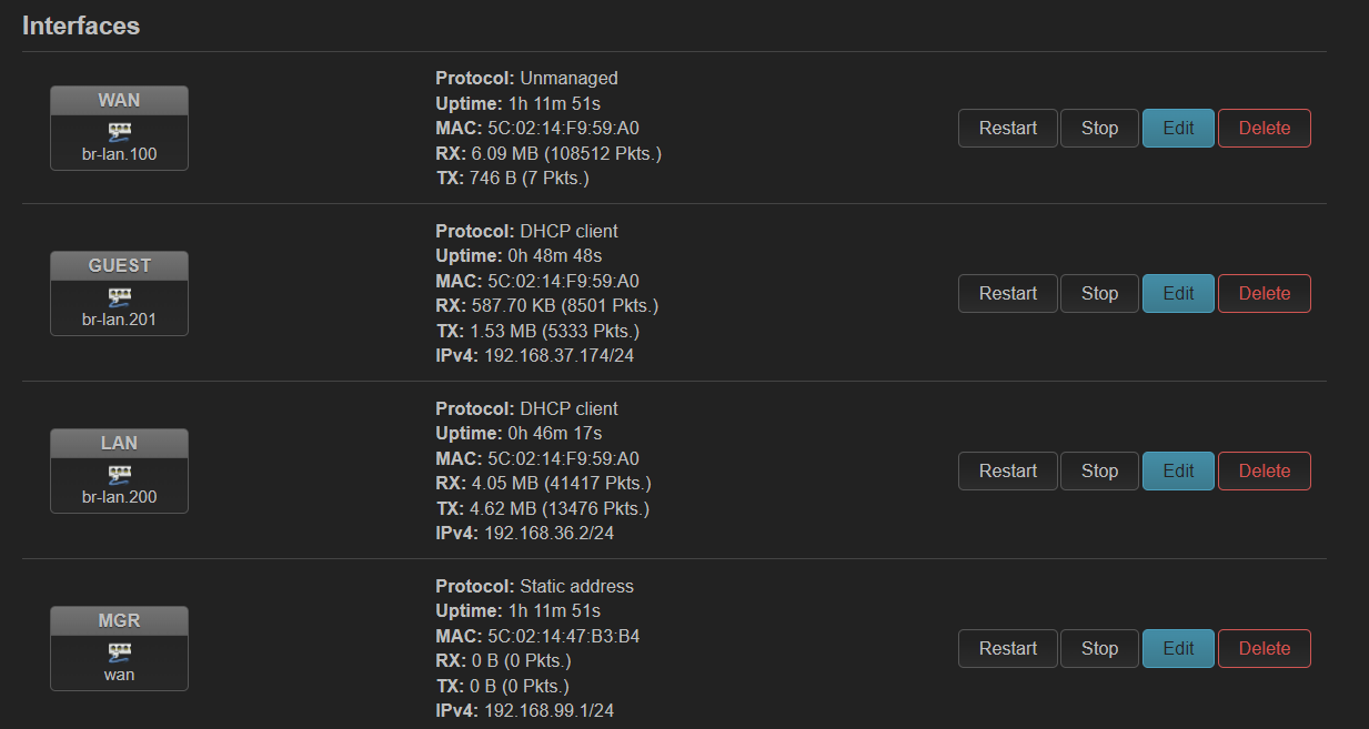
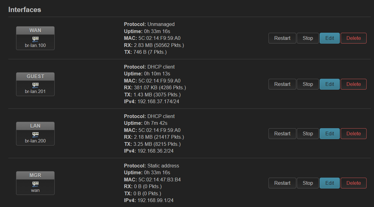
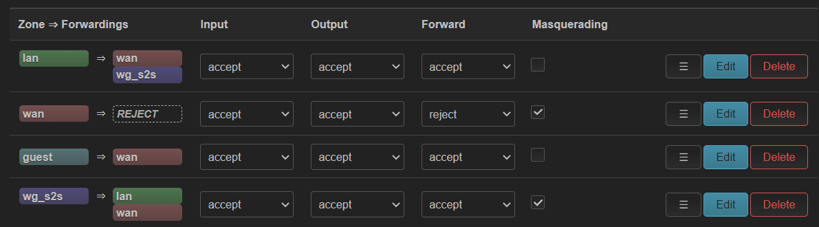
在 ax6s 上创建了一个 guest wifi,使用单独的 vlan。最终效果如下:
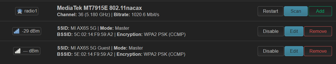
但是创建过程中不知为何 guest 显式设备不存在,于是手动添加了 802.1q 设备,vlan id 手动指定为 201。貌似没有和 br-lan 中 bridge vlan filtering 自动创建的 802.1q 产生冲突。于是设备不存在的问题解决了。
但是 guest 仍然无法通过 dhcp 获得 ip。tianyi 的 br-guest 也无法获得 ip 地址(其中 215 是手动添加的,234 是后面成功后自动获得的),tcpdump -i br-guest 可以看到有来自 ax6s guest 接口的 dhcp request。
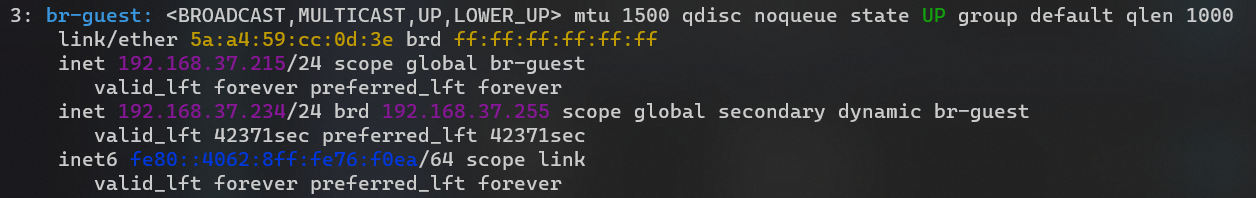
进入 op2,发现也没有生成对应路由,而是全部走 192.168.36.1(图中的 default 和 192.168.37.1 是后面自动生成的),于是手动添加了一条 192.168.37.0/24 的规则。
default via 192.168.36.1 dev br1 proto dhcp src 192.168.36.215 metric 100
default via 192.168.37.1 dev br-guest proto dhcp src 192.168.37.234 metric 100

192.168.37.0/24 dev br-guest proto kernel scope link src 192.168.37.215
192.168.37.1 dev br-guest proto dhcp scope link src 192.168.37.234 metric 100
但是此时 ax6s 还是无法 dhcp 获得 ip,于是手动添加了一个 37.180 的地址,发现仍然 ping 不通 37.1
检查 op2,发现 guest 无法访问路由器自身因此无法 ping。于是开启了 input(之后又关闭了,没问题)
此时发现 guest 已经可以上网了。不知道上面步骤中哪一步导致的。